 English
 русский
 italiano
 español
 português
 العربية
 Melayu
 ไทย
 Tiếng Việt
 Українська
 中文


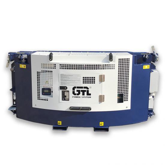
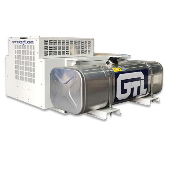
Universal conversion manual switching mode Manually change the copper bus way Dual power switching changes winding wiring
1.3 Configuration of Multi-Voltage Generator Sets
A. Universal conversion manual switching mode: main circuit breaker for the generator set (rated current calculated from the minimum voltage segment and lowest number of phases), universal transfer switch, cabling connecting the main circuit breaker to the universal transfer switch and the switch to the generator, multi-voltage control system protection features, and AVR wiring adjustment.
B. Manual copper busbar reconfiguration mode: main circuit breaker for the generator set (rated current calculated according to the minimum voltage segment and lowest phase count), multi-voltage switching insulation boards, cabling connecting the main breaker to the insulation board and the board to the generator, multi-voltage control system protection, and AVR wiring adjustment.
C. Dual power switching winding reconnection method: main circuit breaker for the generator set (rated current calculated according to the minimum voltage segment and lowest phase count), 2 dual power switches and associated control components, cabling between the main circuit breaker, dual power switches, and generator, multi-voltage control system protection, and AVR wiring adjustment.
1.4 Alternator Selection Requirements for Multi-Voltage Generator Sets
The working principle of multi-voltage switching: Based on reconfigurable 12-wire generator windings and standard alternator wiring schematics, the system outputs: 1. Series star winding output: 380V-415V/50Hz and 380V-480V/60Hz; 2. Parallel star winding output: 190V-208V/50Hz and 190V-240V/60Hz; 3. Double delta winding output: 220V-240V/50Hz and 220V-240V/60Hz.


